
Steel fabrication drawing is a process of creating a diagram or illustration that shows how steel components will be assembled together to create a finished product.
This type of drawing is used by fabricators and manufacturers to plan and execute the manufacturing process. The finished product can be anything from a simple bracket to an entire building.
BOM – Bill of Materials
Steel fabrication drawing begins with the creation of a bill of materials (BOM), which lists all the components that will be used in the finished product.
The BOM is then used to create a schematic diagram, which shows the relationship between the individual components. The schematic is then used to create a more detailed drawing called a fabrication drawing. This drawing shows the exact dimensions and location of each component.
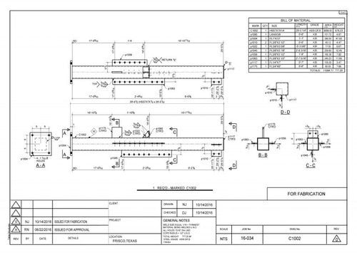
The fabrication drawing is then used by the fabricator to create the finished product.Fabrication drawings can be created manually or using computer-aided design (CAD) software. Manual drawings are typically more accurate, but CAD drawings are easier to modify and update.
Thanks for reading! Steel fabrication drawing is a process of creating a diagram or illustration that shows how steel components will be assembled together to create a finished product.
This type of drawing is used by fabricators and manufacturers to plan and execute the manufacturing process. The finished product can be anything from a simple bracket to an entire building.
The building process starts with an architect who designs the structure in terms of materials, finishes, and size.
The structural engineer’s calculations are based on this information before they produce drawings for fabrication technicians to use when completing their jobs- these cannot simply be made by either architectural or engineering firms alone!
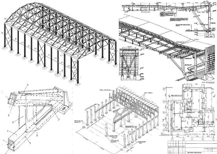
3D Fabrication Modelling
The use of advanced CAD (computer-aided software) tools to develop sophisticated steel drawings is one way that structural steels are detailed.
3D models created with these programs can be used across many industries for various purposes, including producing General Assembly drawings like those seen on building blueprints or site plans which show how the structure will look when completed.
Steel detailing software is beneficial to architects, engineers, and fabricators because it allows them all to work together more efficiently.
The 3D designs can be used as input for accurate fabrication materials which means less time spent on guessing what you need that won’t end up costing anything extra once construction begins!
Avoids errors and delaysThe perfect tool for professionals, avoiding errors and delays – Good CAD 3D steel detailing software specifications every fabrication sheet to be displayed as a visual presentation of the structure with all parts managed efficiently.
If there are any model changes needed on it then these can easily come about through just editing one drawing instead than multiple manual execution time-consuming tasks!
Cost-saving measure
The 3D steel detailing software allows for an alternative model of the structure, which can save you on labor and material costs. You will even have a chance at calculating how much structural steel is necessary- potentially leading up to saving both ways!
As Advised
With a decade-long experience and proven track record in high-profile commercial infrastructure projects, Adviser has been able to deliver cost-effective service for not only their customers but also themselves.
With these qualifications under his belt, the fabricator will be better equipped than most when faced with tighter construction schedules or longer material lead times.
Conclusion
Overall, fabrication drawings provide an extremely important service for anyone involved in the manufacturing and construction process. By reducing errors and facilitating communication, these drawings can save time and money while ensuring a high level of quality in the finished product.
Steel fabrication drawing is a process of creating a diagram or illustration that shows how steel components will be assembled together to create a finished product.
This type of drawing is used by fabricators and manufacturers to plan and execute the manufacturing process. The finished product can be anything from a simple bracket to an entire building.