
It’s a programmable logic controller or PLC for short. It’s a programmable unit, essentially a minicomputer tailored to automate and regulate one particular process. Valves being opened and closed, temperatures being adjusted, and flows and pressures being managed are all examples. Burraq Engineering solutions is an Engineering institute that provides the best PLC Training in Lahore. A PLC is able to carry out a wide variety of operations in response to predetermined triggers, such as the passage of time or the occurrence of other events. A PLC has more input and output ports than a typical computer. Mechanical relays and their control systems came before PLCs.
Electromechanical functions
Because of their size and complexity, these solutions were not suitable for use in tight quarters. Instead of physically altering the connections, as with mechanical relays, the PLC comprises miniature digital relays or transistors that are programmable by software. This requires significantly less physical room and is simpler to operate and modify as needed than a mechanical alternative. Programmable Logic Controller is an acronym for this device. These computers are meant for use in industrial settings, such as a factory or a plant, where they can be programmed to manage a wide range of electromechanical functions.
Electromechanical relays
There is a wide range of sizes and shapes available for PLCs. While some may be carried around in a pocket, others are so enormous that they need their own sturdy stands. Breadboards and function modules can be added to some PLCs to allow for customization for a wide range of uses in the industrial sector. PLCs are used in many fields due to their versatility, efficiency, and simplicity. Ladder logic, which is based on electromechanical relays, is just one method of programming programmable logic controllers; other methods include specially adapted versions of BASIC and C.
SCADA and HMI systems
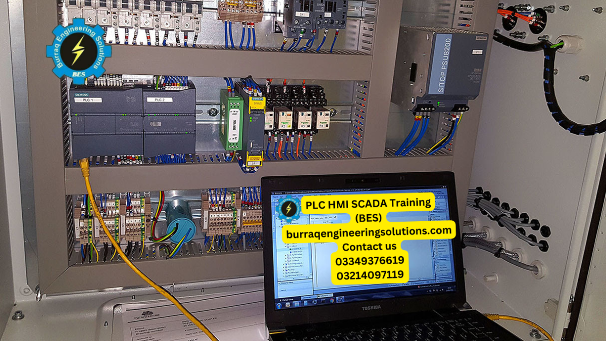
These days, PLCs typically run on one of five different programming languages: ladder diagram, structured text, function block diagram, instruction list, or sequential function diagrams. PLCs are the main hardware component of SCADA and HMI systems, allowing users to view data from the production environment and providing an interface for users to input control data. PLCs are the conduit through which the SCADA or HMI system communicates with the plant or manufacturing machinery. Assembly lines, machine operations, and robotic equipment are all examples of automated processes that might benefit from the use of programmable logic controllers (PLCs).
Equipment and sensors
Input, output, and central processing unit are the three primary types of PLC functions. The inputs to which machines and other equipment are linked are monitored by PLCs, which collect data from the production plant. The central processing unit (CPU) then takes the incoming data and applies logic to it depending on the state of the input. The CPU then runs the code written by the user and communicates with the peripheral devices via data or commands. Inputs can be broken down into two categories: those provided by devices and machines, and those provided by humans. The PLC receives data from many equipment and sensors.
Physical switches
Physical switches, buttons, and encoders are all examples of inputs that can have on/off states. Things like temperature, pressure, and liquid level sensors, as well as pumps and readouts, can have either an open or closed state, respectively. Presses on keypads, touch on screens, and swipes on card readers are all examples of user-initiated inputs. PLC logic then takes these inputs and produces an output, which may be a physical action or an image. Motor starts, the light turns on, valve drains, pump heats, and pump stops are all examples of physical outputs.
Programming terminals
Printers, projectors, global positioning systems, and displays all receive visual outputs. Control cycles are used in PLCs. The PLC begins by checking the status of all input devices. The user-defined logic is applied by the PLC and carried out in accordance with the current states of the inputs. The PLC then sends on/off commands to any connected output device. After completing these steps, the PLC will conduct a safety check by exchanging data with its onboard diagnostic and programming terminals to ensure everything is working as it should. After each iteration is done, the PLC begins the process again.